

 ABSTRACT
As the appetite of modern society for electricity continues to grow, so does the desire of power plant managers to increase the reliability of their plants. The main piece of equipment used by power plants to produce electricity is the turbine; if it does not run, the plant does not produce electricity. The most common types used in power plants are gas turbines and steam turbines. Aside from turbine blade failures, the most common turbine reliability problems are bearing and control system failures, which often can be traced back to lubrication-related problems.
A turbine lubrication reliability programme should be an integral part of any power plant maintenance programme. In recent years, significant attention has been given to varnish formation in power turbine lubricating systems. This paper will focus on varnish and other problems seen in steam turbines and will offer suggestions for how operators can overcome them.
Introduction
To satisfy the ever-increasing demand for electricity, all power plant operators are interested in improving the output and reliability of their plants. They accomplish this primarily by ensuring that the power-generating turbine operates as frequently and efficiently as possible. Many of the problems that result in turbine downtime are lubricant-related, making it imperative that power plant management and maintenance groups work together to develop a turbine lubrication reliability programme for their plants. Of the different types of turbine used for electricity production, steam-driven are among the most common. Though there are similarities between the different turbine types and the lubricants used, there are specific differences. A steam turbine reliability programme should be multifaceted, including functions such as lubricant selection, lubricant condition monitoring, lubricant storage and lubricant supplier service. Recent evidence from field performance and research studies suggest that it is possible to overcome many steam turbine lubrication problems through selection of a well-formulated turbine lubricant, accompanied by an entire programme to ensure successful service of the lubricant.
Background
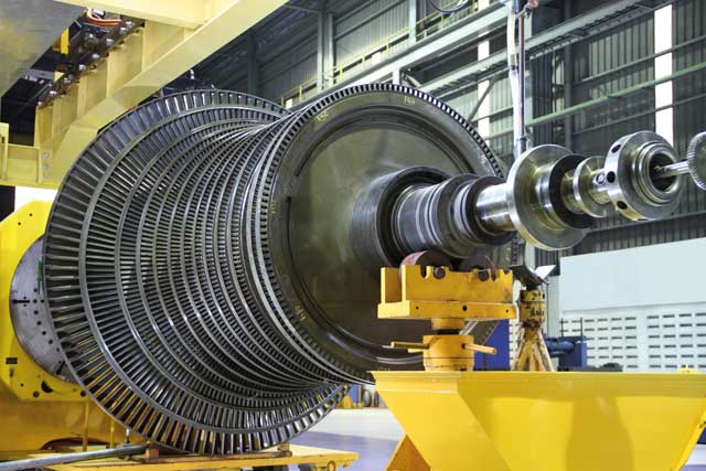
In simple terms, a power turbine is a device that converts rotational energy into electrical energy. The rotational energy comes from various sources from which each type of turbine derives its name, such as steam turbine, gas turbine, wind turbine and hydro turbine. This paper focuses on steam turbines. In this type, water is heated by various means, such as burning coal or through a nuclear reaction, until it becomes steam. The steam travels through blades attached to a shaft, causing the shaft to turn. The rotational energy is transferred to a generator that produces electricity.
The turbine shaft rides on several lubricant-filled bearings. These are usually simple bearings into which the lubricating oil is pumped under high pressure. The oil lubricates the bearing hydrodynamically, bearings and shaft being separated by a pressurised film of oil to prevent any metal-to-metal contact.
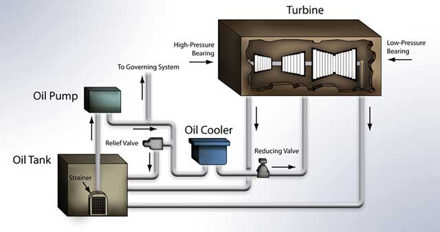
Figure 1 is a simple illustration of the general components and travel route of the oil in a steam turbine lubrication system. Along with providing lubrication to the shaft bearings, the oil also lubricates the oil pump, and in some systems is used as a turbine control fluid in the hydraulic governing system. Many steam turbines have an isolated governing system that contains its own fluid. In order to ensure that the high-pressure lubricant is properly supplied to the bearings, it is pumped from an oil reservoir, through an elaborate system of flow control valves, an oil cooler, through the bearing, and finally back to the reservoir. The oil is constantly agitated as it circulates through the system. This is important to note, as it provides both benefits and challenges for the oil during its lifetime in the turbine.
Lubricant formulation
In its simplest form, a lubricant can be described as having two major components: base fluid and additives. Compared with other lubricant formulations, such as those of engine oil, turbine oil formulations are considered rather simple. Table 1 provides a summary of common turbine oil components. For example, engine oil formulas often contain as much as 10 to 20% additives, while most turbine oils will generally contain only 0.5 to 1.5% additives.
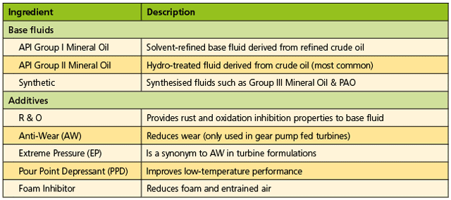
“Additive” is here a broad term for various components added to the base fluid to provide specific performance benefits while the lubricant is in service. Maximum turbine oil performance provides optimum turbine performance. If the wrong turbine oil is selected, the turbine operator can experience a variety of problems. More details will be supplied on what to look for in steam turbine oil formulations later, but first it is important to consider the problems steam turbine operators experience.
Steam turbine problems
Since the late 1880s the oils used to lubricate steam turbines had seemed to provide reliable performance with few problems Those that did occur were generally very predictable and were often caused either by poor maintenance practices or overextending the life of the oil.
In recent years, this trend has seemed to change. Why? In the late 1990s, shifts were made both in operating conditions and in steam turbine oil formulations that began to cause a variety of problems for steam turbine operators. Operators, test laboratories and the lubricant industry have conducted significant research and most have concluded that the cause of the problems is the increased use of API Group II base oils in turbine oil formulations combined with increased use of steam turbine peaking operation.
The problems with the highest profile are:
- Entrained air and foam
- Loss of demulsibility
- Formation of sludge and varnish.
Entrained air and foam
The difference between foam and entrained gas (usually air) in turbine oil is difficult to describe. A “beer analogy” can be used as a visualisation aid. When beer is poured into a glass, a bubbly head floats on top of the beer, and there are gas bubbles in the beer. The head on top is an example of foam, while the bubbles in the beer’s body are an example of an entrained gas. The only problem with this analogy is that the foam on the beer is a good thing, while foam on turbine oil is not. The question is how do gases get into the oil in the first place?
As mentioned previously, steam turbine lubricant circulates through an elaborate system of pumps, pipes and bearings. During use, the oil moves from areas of high pressure to low pressure, flows and splashes through twists and turns in the turbine piping, and temporarily lies almost static in the oil tank. There are many opportunities to agitate gases into the oil. If there is no opportunity for gas to escape from the oil, it becomes entrained.
When the oil reaches low agitation areas, such as the oil tank, the buoyancy of the gas bubbles allows them to rise to the oil surface where they can be released. Unfortunately, steam turbine operators often notice that instead of being released, the bubbles float on the surface of the oil as foam.
When either foam or entrained air develops in steam turbine oil, it can result in catastrophic effects on the turbine oil, turbine bearings and hydraulically-controlled governing systems.
The lubricant’s primary job is to minimise wear by lubricating the moving parts in the turbine. Gases are not very efficient lubricants. They do not possess the film strength to keep the moving parts from rubbing together. Besides providing wear-reducing properties, oils have secondary purposes, such as heat transfer, corrosion protection and contamination transportation. Entrained gases can negatively affect these properties as well.
The most common gas present in steam turbine oil is air. Nitrogen is the highest concentration gaseous component of the air, but oxygen is the most damaging. Oxygen reacts with the base fluid and breaks it down through oxidation. The more oxygen there is in the oil to cause oxidation, the more the oil will be degraded and its lifespan reduced.
Loss of demulsibility
Another gaseous component of air that can be as damaging as oxygen is water vapour, which can be drawn into the turbine oil where it can condense and collect over time. Entrainment is generally a very slow route of water ingression; more rapid routes are through cooling bundle leaks and steam leaks through bearing seals. Regardless of the route by which the water finds its way into the oil, it is a very damaging contaminant.
Water exists in three forms in industrial turbines: free water, dissolved water and emulsion. Free water is water that separates from the turbine oil and collects in pools in the low areas of the turbine and of the oil reservoir. Free water is the easiest form of water to remove from a turbine because it is present as a separate layer below the turbine oil.
Dissolved water cannot be easily separated. Water and oil usually do not mix, so the concentration of dissolved water in new oil is rather low.
Emulsion is a stable, milky mixture of oil and water that is difficult to separate. It differs from dissolved water in that it is almost a gel-like dispersion of water droplets in the oil. Although not easily removed, it is much easier to remove than dissolved water.
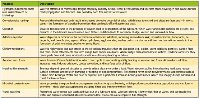
Water in any of these three forms can result in problems for the turbine and the turbine oil that could result in reduced lubricant life, shorter equipment life and mechanical control problems. Table 2 provides a list of these problems and a brief description of each.
To manage the many problems that water contamination can cause in power generation turbines, operators have adopted a variety of techniques. One of the often overlooked solutions is lubricant selection. Many operators assume, “Oil’s oil, what difference will the oil make? Oil and water don’t mix anyway.” Unfortunately, these same people often discover that this statement is untrue.
The various techniques they employ to remove water from in-service oil meet with limited (if any) success. The reason seems to be that the affinity of the oil to water has changed. Field evidence is mounting that suggests turbine oil selection may play a key role in the success of water removal techniques.
Why does the affinity of turbine oil for water change during service? Water is considered a polar compound. There is a general rule in chemistry that states “like dissolves like”, implying that water is easier to dissolve in other polar compounds. Oil is a complex mixture of compounds made up of various hydrocarbons that are nonpolar.. Scientifically, this is why oil and water would not mix.
Yet turbine operators have had problems removing water from in-service oils, indicating a change in either the water or the oil. Did the water become less polar, or did the oil become more polar? Under normal conditions, it is nearly impossible to make water nonpolar, so it must mean that oil becomes polar. A polarity shift mechanism occurs in a turbine while it is in service that results in increased turbine oil polarity. This increases the amount of water that can be dissolved into the oil.
The chemical reactions that cause this change in the oil are complex, but the process can be described in a simple four-step mechanism that results in the polarity increase of the turbine oil:
- Step 1: Infiltration
- Step 2: Catalysis (galvanic reactions)
- Step 3: Oxidation & hydrolysis
- Step 4: Emulsification.
Formation of varnish and sludge
Inlet steam temperatures can be in the range 216-288°C. Some of this temperature is transmitted to the turbine main bearings, producing the perfect conditions for accelerated deterioration of the oil, especially when contaminants are introduced into the oil. When steam turbine oil is exposed to entrained gases, water contamination and elevated temperatures for extended time intervals, it causes thermal breakdown, oxidation and hydrolysis of the oil that ultimately results in advanced forms of lubricant degradation called sludge and varnish. Certain additives – called antioxidants or oxidation inhibitors – are included in steam turbine oil formulations to help improve oxidation stability. Unfortunately, the use of improper antioxidants has also been shown to contribute to sludge and varnish formation.
The oxidation mechanism for lubricants has been well documented. Oxidation is the reaction of lubricant base stock with oxygen, which leads to degradation byproducts forming in the lubricant. The following is a simplified depiction of this process.
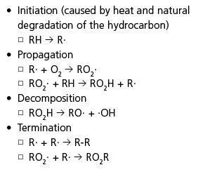
“RH” represents a hydrocarbon molecule, such as oil. “R·” is a hydrocarbon free radical. “O2” is oxygen. “RO2·” is an alkylperoxy radical. “RO2H” is a hydroperoxide (sometimes called a carboxylic acid). “RO·” is an alkyloxy radical. “·OH” is a hydroxy radical. “RO2R” represents nonradical products. R-R represents polymerised hydrocarbons formed when two hydrocarbon free radicals react. The outcome reactions are the formation in the oil of oxygen-containing products such as acids, esters, alcohols, ketones, polar compounds and polymeric materials.
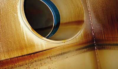
It was stated earlier in this paper that oxygen is polar, like water. Metal parts of a steam turbine are also polar. Polar compounds are attracted to one another; degraded lubricants can have a heightened affinity toward the metal turbine parts, where they will collect as a sticky plastic-like material called varnish, as shown in Figure 2.
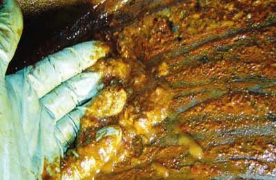
Antioxidants function by reacting with lubricant degradation precursors during the propagation or decomposition stages, thereby slowing down the attack of the oil by oxygen. Sometimes, degraded antioxidant compounds (especially PANA – phenyl-alpha-naphthylamine – types) can also begin to accumulate into high molecular weight materials in the oil and deposit on metal parts as varnish. When large quantities of varnish accumulate in the body of the oil, they begin to precipitate out of solution into a thick viscous layer called sludge, as illustrated in Figure 3.
Hydrolysis is another degradation mechanism by which varnish and sludge are formed in a turbine. It is a reaction of oxygenated esters and ketones (in used turbine oil) with a hydroxy group in water. (In a process called dissociation, water naturally breaks down into a weak acid and a hydroxy group.) Hydrolysis occurs as a reaction between the used turbine oil and the hydroxy group to make the lubricant have a stronger affinity to water and to metal turbine parts. This reaction step also increases the oil’s tendency to emulsify with water, thereby increasing the rate of oil degradation and making water removal even more difficult.
The previous discussion may lead a steam turbine operator to ask, “Given all of these problems with the turbine oil, how can I run my turbine reliably?” Fortunately, there are solutions.
In Part 2 in our next issue, Lubrication reliability programmes, oil purification and oil condition monitoring.
Sources / Recommended Reading
1. Moehle W, Ghatto V, Livingstone G and Wooton D, Practical approaches to controlling sludge and varnish in turbine oil, Lubrication Excellence 2007 Conference Proceedings, Noria Corp., May 2007.
2. Micetic J and Beitelman A, Performance problems with Group II hydro-cracked turbine oils in Corps of Engineers hydropower facilities, US Army Corps of Engineers, Engineer Research and Development Center, 2004.
3. Fitch J, How water causes bearing failure, Machinery Lubrication, Tulsa, July 2008.
4. Rizvi Syed, Lubricant additives and their functions, ASM Handbook (Volume 18), ASM International, 1992.
5. Troyer D, Removing water contamination, Machinery Lubrication, Tulsa, May 2001.
6. Eachus A, The trouble with water, Tribology and Lubrication Technology, Society of Tribologists and Lubrication Engineers Publishing, October 2005.
7. Livingstone G, Ameye J and Thompson B, Rethinking condition monitoring strategies for today’s turbine oils, Machinery Lubrication, Noria Corp, May/June 2010.
8. Troung N,. Today’s varnish control technologies, Practicing Oil Analysis, Noria Corp., November 2007.
9. Wagenseller G, Fluid analysis critical to maximizing lube-oil service life, Combined Cycle Journal, Fourth Quarter 2009.
 John Sander, VP of Research & Development, Lubrication Engineers, Inc, has a BS in chemistry from Wichita State University and an MS in environmental science from Friends University. In 1989 he began his career at Lubrication Engineers, where he has been responsible for a variety of lubricant quality, formulation and testing activities. He holds CLS and OMA I certifications from STLE, and a CLGS certification from NLGI. His memberships include SAE, NLGI, ACS and STLE. He has authored or co-authored 20+ technical and marketing papers and one book chapter. He is a past winner of the NLGI Author Award.