

ABSTRACT
In his third note on machine balancing (see Issues 3 and 6 of Volume 13) Ray explains the ‘components method’, describing its application to the rotor of a constant speed, induced draft, centrifugal fan on a power station boiler.
Among the methods of balancing mentioned in the table in my first article on this subject (Balancing using your mobile phone, Vol.13, Issue 3) is the “components method”. This was developed for balancing a rotor that was considered too long to be treated as a single plane, but was too short for two-plane treatment.
The machine was a constant speed 590 r/min double entry centrifugal fan, one of two Induced Draft fans in parallel on a large power station boiler. The power station had 16 of these fans, handling hot wet gas at around 200°C with output controlled by variable inlet vanes on each entry.
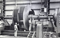
Figure 1 shows the relative size of its impeller: 3.4m diameter, 8.75m between bearings, 22t mass, 1780kW.
Unbalance resulted from dust particles building up on the blades and, over the longer term, from erosion. Condition monitoring by vibration analysis showed an increase in vibration at 1× (i.e. at the frequency of rotation). It was decided to attempt on-load cleaning. Both entry areas of the fan were below atmospheric pressure, and were fitted with a hopper and piping arrangement. A heap of dry coarse sand was ordered and dumped at the hopper area. Sand shovelled by hand into the hoppers was drawn in to the fan, with the success of cleaning shown by a reduction in vibration.
For field balancing, a visible part of the shaft was marked with reference numbers evenly spaced around the shaft, as would be done for a single plane balance.
In the “influence coefficients” method, that is usual for long rotors, a calibrating mass would be placed on one end and a second test run made. It would then be removed and located on the other end for a third run. The size and positions of masses to balance can then be calculated, usually by software methods. The components method uses one less run, meaning a shorter time off line. It also enables a visual impression of progress.
BALANCING PROCEDURE
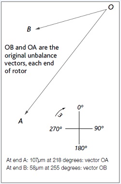
With the fan in service, but with inlet vanes and outlet dampers closed, the initial run was made, and the 1× vibration amplitude and phase measured at each bearing. The vectors were plotted as in Figure 2.
At end A: 107 µm at 218 degrees: vector OA
At end B: 58 µm at 255 degrees: vector OB
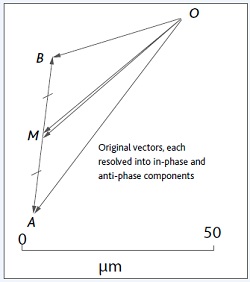
These vectors can be resolved into many combinations of in-phase and anti-phase components. If the rotor and its supports are regarded as symmetrical end-to-end, then the vectors are resolved into components of equal length. This was the case here, so the original vector OA was considered replaced by vectors OM and MA, with vector OB replaced by MB (which is anti-phase (i.e. opposite, to MA) and OM, which is equal to the parallel OM, as shown in Figure 3.
Here the two in-phase components were larger than the anti-phase ones, so balancing proceeded using a shared pair of masses. U-bolt clamps were used as calibration masses, mounted on each inlet flaring, in the same angular position on each end.
After calculation and installation of the balancing masses, the vibration would be expected to be anti-phase, with the corresponding residual vibration to scale of components MA, MB. Here the vibration after balancing was expected to be 35 µm, and considered acceptable.
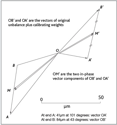
If the original vectors were much larger in anti-phase than in-phase, then the pair of masses would be placed on the impeller, one on each end as before, but 180 degrees apart in phase to give a couple effect (see Figure 4).
At end A: 41µm at 101 degrees: vector OA´
At end B: 84 µm at 43 degrees: vector OB´
The in-phase components, OM ´, of these vectors are found as before, and used to calculate the size of the masses to balance as done in single plane vector calculations. (Note that AA´ and BB´ which are the effect vectors of the calibrating masses on ends A and B respectively are closely parallel).
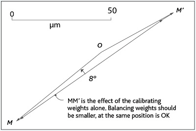
Figure 5 shows only the original and calibrating vectors.
By scaling, the mass to balance, if installed at that location, should be reduced in proportion by 77/134 ×1360g = 780g. The angular location was close to that used for the calibrating masses.
The location for minimum balance mass size was near the outer edge of the inlet shrouds where the balance masses were installed during the factory balance. The size of the masses required on this occasion was reduced in proportion to the relative radii at this location and the calibrating mass location.
The factory masses had been welded, followed by heat treatment. For field installation, welding was not allowed on the alloy steel shrouds, so holes had to be drilled to bolt on the balance masses. The first hole took over an hour – what a hard steel we thought! The fitter got a new drill – and it took only 5 minutes for the second hole!
This method is essentially the same as that for balancing a flexible rotor with a limited choice of balancing planes. The vibration at around the first critical speed would be mostly in-phase, and near the second critical speed, mostly anti-phase.
INCREASING FAN PERFORMANCE
As a boiler fouled with ash deposits the system resistance increased to the point that the fan controls opened fully. This limited and reduced unit load, so another engineering job on these fans was to increase their output. From the fan’s Static Pressure-Power-Flow curve, the maximum overloading power was observed to be about 140kW below the motor rating. This gave the possibility of increasing the impeller diameter. The larger diameter was calculated using the same method as for trimming pump impellers. Extension tips, some 35mm long, were welded on to the blades. This was done so precisely that balancing afterwards was not needed.
UNBALANCE MAY NOT BE THE PROBLEM!
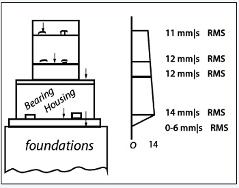
Another fan in similar duty showed high vibration and balancing was attempted but without success. It was tried with the fan both hot and cold, and the fan was accused of having a “rogue” rotor! A closer check with an overall level vibration meter revealed that the bearing anchor bolts were loose. The Figure 6 sketch shows the relative amplitude measured horizontally up the height of the pedestal and bearing housing. To be fair, the holding-down bolts were beneath a grid mesh floor section and covered in years of oil absorbent.