

ABSTRACT
Current research is being carried out by the US Navy to quantify reliability in scientific terms, where the terms of reference are ‘The present study relies on a science-based explanation of damage as the source of material failure, and develops an alternative approach to reliability assessment based on the second law of thermodynamics’. Current reliability calculations are predisposed to a single failure mode or mechanism and assume a constant failure rate, while this research implies that reliability is a function of the level of damage a system can sustain, with the operational environment, operating conditions and the operational envelope determining the rate of damage growth. This article explores the areas where we can control significant levels of damage in order to improve system reliability.
Background
There is currently research being carried out – http://crr.umd.edu/sites/default/files/documents/anniv25/posters/RE25th-Poster-Imanian.pdf that is being funded by the US Navy to try and quantify reliability in scientific terms.
The terms of reference for the research are ‘The present study relies on a science-based explanation of damage as the source of material failure, and develops an alternative approach to reliability assessment based on the second law of thermodynamics.’ In effect it is looking at how the dissipation in entropy can be equated to the level of damage in a system, and as the damage grows it increases the likelihood of failure which in effect reduces the reliability.
Reliability in an engineering context is the ability of an item to perform a required function under given conditions for a given time interval. It is generally assumed that the item is in a state to perform this required function at the beginning of the time interval, and reliability performance is usually expressed as a probability. For example an electrical relay may have a 99% probability that it will achieve 100,000 operating cycles at full load.
Taking the example of the relay a step further: based on the operational environment (no impact), operating conditions (full load switching) and operational envelope (four cycles per minute, 24/7/365) we should be able to calculate the level of damage growth over time to predict an individual MTBF for this component of 17.4 days with a 99% accuracy.
Current reliability calculations are predisposed to a single failure mode or mechanism and assume a constant failure rate. For the relay example this might be arc damage on the contacts, but spring failure or coil overheat could also be possible. The problem is that for every component there will be several failure modes or mechanisms and each of these would generate their own failure predictions resulting in an incoherent reliability calculation. The entropy-based failure prediction, on the other hand, takes all of these elements in order to determine a level of damage and is then used to calculate the life of the component.
Reliability therefore becomes a function of the level of damage a system can sustain (let’s call this resilience), with the operational environment, operating conditions and the operational envelope determining the rate of damage growth, i.e.
Reliability (R) = Resilience (X) – Damage (D)
Creating Resilience
We have all heard of satellites that have been operational for many years, without any human intervention. This is an indication that resilience is a function of the creation of the equipment or system and is not necessarily driven by human intervention. Taking the relay example, suppose that we select one with an average life of 5,000 cycles, and we use it in the same application. Ultimately we have built in a failure mode with an MTBF of 0.86 days. I’m sure we would all agree that this would be an inherently unreliable system based on this component failure, as the level of attention and repair required is excessive.
In order to improve the reliability of the system we therefore have to review the design. If we now select a relay that has an average life of 200,000 cycles, the MTBF increases to 34.7 days, which although still unreliable, is much improved on the first option. Fundamentally though, this design is flawed as the duty cycle on the relay is excessive and in order to improve the resilience of the system we need to change the design. Other ways of doing this would be to reduce the number of activations, alternating the activations between multiple relays, or eliminate the requirement for the activations.
Once the design is completed, the resilience creation moves into a new phase where the design is implemented. Unfortunately this is where we start eroding the resilience as opposed to enhancing it. This is caused by several factors:
Material selection differs from the material specified during the design phase. Invariably this is driven by price with some form of ‘value engineering’. Quite often the reasoning behind the designer decisions or selection of components is forgotten or ignored, and as a result the components no longer meet the design requirements. Taking the earlier example, the best priced option could well be the unit with an average life of 5,000 activations as opposed to the one with 200,000 activations. There is nothing wrong with value engineering as long as it does not corrupt the design intent.
Defective materials as a result of manufacturing defects. Manufacturing defects should be picked up during quality control inspections throughout the manufacturing process. Having said that, some manufacturing defects could be so deep rooted in the component that it would be virtually impossible to detect, and the level of detection gets reflected in the price. These usually result in early component failures or shortened life expectancy of individual components, and could easily result in extensive re-work to replace the defective components.
Defective materials as a result of lack of care during the delivery process. Delivery process covers everything from the handling of the component at the manufacturer, to the transportation, storage and finally the handling of the component on the installation site. Managing the level of care during this process is, however, a lot more difficult, as we need to consider items such as shock, vibration, environment and storage conditions. Lapses in these controls would also usually result in early component failures or shortened life expectancy of individual components similar to those as a result of manufacturing defects.
Improper or poor installation of components or equipment. We all know from our experience that an incorrectly installed bearing, or installing electronic components without the correct ESD protection, can both result in a shortened life expectancy as a result of the damage caused to the component. The future reliability of the system is dependent on the level of care applied during the installation, not only in terms of the method of installation, but also in the diligence during the instillation. Examples of this would be poor wiring connections resulting in connector failures or incorrectly set up equipment resulting in excessive wear. Invariably, these are usually as a result of poor management of the installation contractors and a poorly executed installation test procedure prior to the equipment or system being brought into operation.
Live testing carried out during the commissioning phase. Commissioning should by rights be a series of progressive tests that prove the system meets the design parameters, however some tests to prove the safety of the system could be quite damaging in order to ensure that the system can protect itself adequately. Consider the impact on a compressor in full load conditions when an estop is pressed. In addition to this level of testing, consider also the length of time it takes to commission a fairly large site with thousands of pieces of equipment all interlinked. In some cases this could be years in a construction environment with significant environmental conditions that do not reflect the normal operating conditions.
Once the system is ready to go into operation, we would already have incurred a level of damage to many of the components which ultimately reduces the level of damage the system can sustain, thus impacting on the system reliability. Expressing it as a mathematical formula:
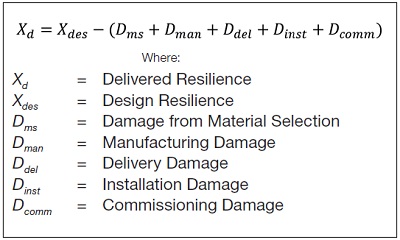
This is the level of resilience that is delivered when new equipment or a new system is installed. Taking this as a point in time, we have the delivered resilience of the system and the only way of improving the resilience is by stabilisation of the operation, the elimination of potential damage caused by poor installation and reviewing control elements, especially in relation to software-related updates in a systemwhere minor software and timing adjustments can be made to improve resilience. What we have usually found is that as a system beds itself in, and these actions are taken, the system will become more resilient (see Figure 1).
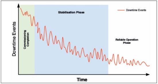
Stabilisation of the operation and software and timing updates are not covered in this paper. However, systems such as our own MIRsystem can assist in identifying areas where these improvements could make the most impact on the duration of the stabilisation phase. From an installation damage perspective, however, we should consider the following condition monitoring activities to identify potential issues that can be remedied:
Infrared thermography to identify equipment that may be heading into trouble in terms of hot spots and upward trends in overall temperature. This works well on electrical motors, electrical connections (over 50V), heat loss or cold areas and failing bearings.
Vibration monitoring to identify unusual vibration signatures and levels as well as rising trends in vibration. This is good for most rotating equipment. However, it is poor in the case of slow rotating equipment and it will be an issue to identify problems with transient vibration caused by equipment that stops and starts frequently. Vibration monitoring on the run-up and run-down of rotating equipment will also highlight any harmonic related issues which might also cause damage if it is not properly managed.
Ultrasound which helps to identify leaks and other unusual high energy noise, such as found on pneumatics, bearings and electrical arcing.
Oil Analysis. Where there is an adequate volume of oil to support this, it could be used to identify systems where there is excessive wear being generated, such as white metal bearings, gear trains or hydraulic systems.
All of these (and there are others) would give you a heads up on the developing level of damage that could be averted if addressed early enough. This would allow you to schedule the repairs in a timely manner to ensure that the resilience of the new system can be raised to the highest possible level when the system is handed over for full operational use.
Maintaining Resilience
Once a system goes into full production, the true art of reliability is to keep the systems running at the correct efficiency and quality output with minimal intervention. In order to do so we need to put processes in place to monitor and limit the growth in damage which ultimately erodes the resilience of the system. Expressing this as a mathematical formula:
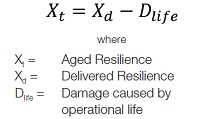
and Dlife is directly proportional to the following elements:
The level of care applied to the system. We know that if we take care of the equipment, identifying failures and taking corrective action prior to them failing, then the equipment or system tends to retain its reliability for longer, because we don’t allow the system to suffer from secondary failures. Take, for example, a gland that comes loose on an electrical panel, when we see it is loose we tighten it reducing the risk of moisture ingress into the panel and limiting the likelihood of corroded connectors. Processes such as defined in NEN2767 can be adapted to quantify the level of care.
The level of maintenance performed on the system. We know from experience that, if you only apply breakdown maintenance on equipment or a system, the frequency of failures will escalate to an unsustainable level. At this point we would be running from one breakdown to the next, almost making it impossible to set a PM programme in place. Alternatively, we could be over-maintaining items to the extent that we could be taking systems off line for unnecessary inspections, purely on the off chance that we can find some hidden failure that might be lurking. Processes such as RCM can be used to define the most appropriate level of maintenance that should be carried out.
Human error and poor workmanship. When components are replaced or we perform any invasive inspection, we introduce the potential for human error. Some research has found that around 70% of equipment failures are as a result of human error. Whether this is as a result of incorrect methodology used to replace the part or re-assemble the equipment, or due to lack of training or skill required for the task, or errors caused by bad practice or poor workmanship. Systems such as our own MIRsystem can be used to monitor before and after a maintenance activity in order evaluate the impact on the system performance.
Replacement parts must conform to design requirements. When replacement parts are purchased, they need to conform to the design parameters, otherwise we have the potential of changing the resilience of the system, similar to the relay selection mentioned in the introduction. In addition to this say, for example, that a system is designed in a way that a particular failure is built in to protect the rest of the system from significant damage. If we change the failing part with one that is more robust, we have in effect changed the design parameters, and as a result we may have moved the failure to another component where it could be far more catastrophic. Procurement processes and component specifications should avoid this possibility. Problems arise, however, when the specifications are not clear or the components are no longer available.
Quick fixes that are not correctly managed. When the equipment or system is running and a failure occurs, we may be forced to apply a quick fix to get the system running in order to meet the demand. If we don’t go back and do a permanent repair to the equipment or system, and we continue to run with the quick fix in place, in the background the cause of the original failure is still present and the level of damage is potentially increasing. This is a cultural issue that is fostered when the maintenance crew are rewarded for their rapid response to issues and not for the long term system improvements.
Using the equipment or system outside the designed parameters. The equipment or system will be designed to perform in a specific manner, and as long as it is used in that manner it will usually perform reliably. When we change the operational processes, and do not change the design intent, the system or equipment may become less reliable and far less efficient. An example of this could be where we design an automated pallet stacker to stack similar sized boxes on a pallet. If we change the process and send variable-sized boxes to the stacker the performance will drop, and as the number of cycles will increase, the level of damage caused by each cycle will increase proportionally.
Residual equipment life. Consider the relay example discussed in the introduction, and assume we have selected the relay which would give us an MTBF of 17.4 days (100,000 cycles) with an accuracy of 99%. On Day 1 of the relay’s life we almost have 100% likelihood of a failure free day, while on Day 16 we would almost have 100% likelihood of a failure. The same would apply to a system, and as time progresses the level of damage on the components will grow to a point where the Aged Resilience is significantly reduced and as a result the system reliability is significantly lowered.
As can be seen from the elements listed above, many of these are within the power of the operators and maintainers to manage and control, while the residual equipment life is more a function of design. Conclusion
As stated in Equation 1, Reliability is a function of the level of damage inflicted on the system, and should therefore, at a point in time, equate to Xt as shown in Figure 2.
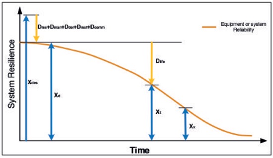
At a point in time (Xx) the resilience of the equipment or system is less than what is necessary to retain the level of reliability that is expected and the system becomes inherently unreliable. In our experience, once the equipment or system has reached this point there is little that can be done to rebuild the level of resilience to support the required reliability. Cost of maintenance at this point starts escalating, as more manpower is required to resolve the number of faults, and as the number of faults increases so does the number of component replacements. Equipment or system availability at this point becomes more a function of manpower and MTTR than of system reliability.
We need to change our perspective on the role of the maintainers. From the items identified above we should see that their role needs to be one focussed on minimising damage to the equipment or system, as this ultimately improves the level of reliability as time progresses. In addition to this we should look to find ways of quantifying the elements within our control in order to predict the level of resilience at any point in time.