

 ABSTRACT
This paper explores and updates the reader on the phenomenon of partial discharge in the context of using it as a reference to help determine the ageing and pathway to failure of high voltage networks. Focusing on cables and switchgear, it uses case studies to show the importance of regular testing or monitoring for partial discharge. It concludes with an insight into the instruments that can be deployed by maintenance teams to help protect on entry into a substation, measure partial discharge and assure themselves that repairs have in fact removed the partial discharge from the HV environment.
In most modern manufacturers, the management of the supply chain has its own department focusing on just in time stock control of the components required to produce their end product.
It is equally common that effective energy management is handled by a facilities management team on a cost to supply basis.
Energy is an essential component whose security of supply is as important as the key elements of your production schedule. It could be argued that to some degree electricity is the ultimate in just in time component: no stock is held, it is delivered to site as need arises and if it fails so does the entire production effort.
This article will address some of the mechanisms and techniques that enable operators of private high voltage networks to reduce the potential for unplanned interruptions, to result in a safer, more economical HV maintenance regime.
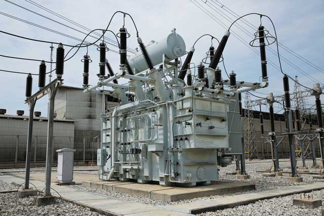
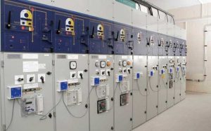
Often, your responsibility starts at the point where electricity enters your site: this is usually described as the main incomer substation and is the point where the distribution network operator’s responsibility for supply hands over to the site. A typical system for a larger private network would have electricity entering this substation at 33kV and leaving at 11kV via cables to the site’s ring main of smaller substations. These small substations are usually interlinked to give some degree of redundancy, and inside them are transformers and switchgear that convert the high voltage to the voltages required by the equipment on site.
There are two main constituents to the HV grid: cables and switchgear. In both, their insulation slowly deteriorates over time until they are either replaced or they fail. This is also true for transformers and, to a lesser degree, overhead lines.
Substation failure can be devastating. Apart from halting production, with the associated crisis management this leads to, it could cause a reportable health and safety incident and in extreme cases serious injuries or fatalities.
Cables, especially underground cables and switchgear, are difficult to test during routine maintenance and need to be isolated before a thorough inspection can be made.
There is, however, a way of identifying those elements that are in danger of failing: partial discharge.
Partial discharge is a phenomenon studied closely in the 1970s. Its definition is
“Localised electrical discharges that only partially bridge the insulation between conductors and which can or cannot occur adjacent to a conductor. Partial discharges are in general a consequence of local electrical stress concentrations usually caused by defects within the insulation or alternatively on the surface of the insulation. Generally such discharges appear as small electrical discharges with durations of less than 1µs”.
Partial discharge is more easily understood as the minute ultrasonic and electrical emissions caused by breakdown of the insulation. Left untreated this leads to progressive deterioration and eventual failure.
Figure 1 shows the characteristic emissions of partial discharge, which include electromagnetic and acoustic emissions and gases.
The advantage of using PD as a way of detecting deterioration in the HV network is that two of the three main telltale signs, radio waves and ultrasonics, can be evaluated without having to enter the HV enclosure.
If you can hear the crackle discharge of PD or smell ozone when you open the door of a substation, our recommendation is not to enter until you have isolated the substation and can remove the risk of an explosion while you are inside.
PD is the most common cause of disruptive failure of switchgear, so its detection and trending will assist you to identify those parts of the network that require more urgent attention. Using simple measuring techniques you can show the rate at which assets are ageing, identify at-risk components and help justify future funding for replacement or maintenance.
Detection
Electromagnetic radiation
The electromagnetic radiation component of partial discharge impinges on the metal cubicle of switchgear and induces a tiny but measurable voltage, called a transient earth voltage (TEV).
This can be measured by a handheld instrument or a continuous monitoring system, both of which are described in more detail in the “Measurement” section below. The choice of measurement device is linked to criticality and cost of failure.
TEV detection is a very effective way of establishing if there is any PD emanating from voids within solid insulation of HV components. (see Fig 2). These voids are almost impossible to identify via any other method.
Ultrasound
The ultrasonic component of PD (akin to the crackle that can be heard if you walk under a pylon line on a misty morning) escapes the enclosures via the many air gaps. It is detectable and can be analysed using a handheld device equipped with a tuned ultrasonic detector such as the UltraTEV Plus2.
It is particularly useful to have a device that can create a fully phase resolved plot in which the PD activity is plotted against the sine wave of the supply voltage being measured. (This capability is inbuilt in the UltraTEV Plus2).
on a phase resolved plot
on a phase resolved plot
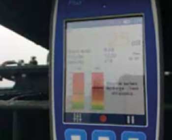
Insulation breakdown leading to a partial discharge event occurs near the peak positive and negative voltage of the sinusoidal waveform – or, for TEV, it may occur on the rising edge of the sine curve. Clusters of activity can be plotted and analysed by the instrument and presented in a graphical form, thus confirming the PD activity as well as its severity.
The screenshot from the UltraTEV Plus2 (Figure 3a) shows PD, and the plot has the characteristic 180 degree apart peaks which are a clear indication of PD. The second screenshot (Figure 3b), though having picked up higher emissions, has been classified by the instrument as noise, perhaps from a radio mast or rotating plant, because of the lack of the symmetry of emissions.
Nitrous oxide
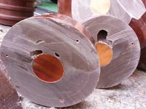
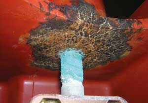
Partial discharge can also lead to the formation of nitrous oxide gas. This reacts with moisture to give the ozone smell and also forms a white residue or verdigris on components. The resulting residue is easy to spot, as shown in Figure 4. However, often an intrusive inspection is needed to find it.
By utilising on-line, non-instrusive detection techniques such as TEV and ultrasound it is possible to scan HV switchgear quickly and pinpoint to a matter of inches where the PD is emanating from. Then the installation can be isolated to allow an intrusive inspection to confirm the presence of PD.
Monitoring and measuring
Recent innovations in PD detection equipment have been applied to both cables and switchgear with very strong evidence-based results. These results are summarised below.
Cables
A study of nearly 200 high voltage cables was conducted, with the cables remaining energised and tested in a non-intrusive manner – the results are shown in Figure 5. The cables were categorised as red, amber or green according to their partial discharge signatures. Of the 17 cables categorised red, over 40% developed a fault within two years. Of the 14 cables categorised amber only 20% developed a fault. Less than 2% of those categorised green became faulty inside a two-year period. Expressed as risk, a cable rated ‘red’ has a near 50:50 chance of a fault occurring within two years. This provides strong justification for any submission for capital expenditure, and equally allows the engineering team to focus on where faults are most likely to happen.
Switchgear
A monitoring system was fitted on a long-term software test to a substation; it was not connected to the outside world as it was mainly installed for software stability tests. The substation failed unexpectedly, leaving 20,000 homes and businesses without power. The data collected during the test (Figure 6) showed that PD monitoring would have given the distribution network operator almost four months’ notice of the failure.
Clearly that length of notice cannot be guaranteed; however, partial discharge monitoring can provide insights to enable adoption of condition-based maintenance regimes rather than relying on traditional time-based approaches. It also provides the evidence to support replacement or refurbishment and assists in the prevention of outages.
It does not, though, remove the requirement for sound engineering decision-making and experience.
Measurement and instrumentation
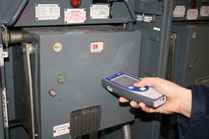
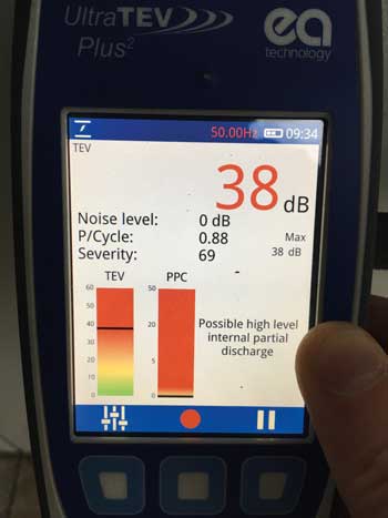
A combination of criticality and funding availability will inform the engineering judgement as to which monitoring solution fits the particular risk profile of a given site. The advantages of the UltraTEV Plus2 handheld PD analyser (Figure 7) are that it provides a cost-effective, very fast and recordable way of assessing the health of network switchgear and cables. This instrument will measure TEV as well as ultrasonic activity; its inbuilt software interprets and reports the results almost instantly, which are exportable via Wi-Fi. Its limitation is that it can only take measurements when in the hands of a technician inside the substation.
For more critical infrastructure a permanent monitoring solution such as the UltraTEV Monitor should be considered (Figure 8): this is more expensive but measures PD continuously, with in-built trend analysis and alarms that can be linked to a SCADA system, a desktop computer or mobile phone.
Conclusion
Whether through periodic inspections to give a snapshot of the health of an asset at that moment, or via continuous remote monitoring to provide trend analysis, PD measurement should be part of your HV maintenance arsenal. It can give you the insights necessary to release the inspection team to carry out more productive tasks and assist in the more effective running of the network.
A cost-benefit analysis to support the case for monitoring should account for the cost of lost production, and the potential cost to brand reputation as well as the cost of the replacement equipment. Far better to try to avoid the crisis in the first place.
In addition to preventive maintenance, the deployment of PD detection equipment also allows for effective acceptance and assurance testing of new installations and repairs.
Partial Discharge monitoring has the potential to be as valuable to maintenance teams as vibration monitoring has become for mechanical equipment. It will add to the engineering data available and potentially reduce unplanned and unwelcome downtime at all types of manufacturing sites.
Case study
The handheld partial discharge analyser UltraTEV Plus2 has been instrumental in fault finding and assurance work of a solar farm.
Recently, during routine maintenance, technicians performed a non-intrusive partial discharge survey using the UltraTEV Plus². The instrument highlighted high PD readings in the substation switchgear cells.
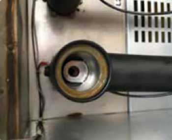
The substation was isolated in order to allow access to the cable compartment. On removal of the cable termination cover, the origin of the high PD reading was not immediately apparent.
The connector was dismantled across all three phases to further investigate the case. Irregularities were noticed on L1.
Without partial discharge analysis, the issue might have gone unnoticed and could have resulted in flashover, rendering the switchgear unusable and the cable requiring re-termination.
 Jason Butler,
Sector lead – industrials,
EA Technology