

ABSTRACT
How much do you know about the condition of your electrical assets? And do you use that information to prioritise maintenance and replacements, so you can reduce outages, increase reliability and safety – and even lower your operating costs?
The importance of understanding the condition of electrical assets has been highlighted by the increasing uptake of PAS 55 across the world. This Publicly Available Specification forms the basis for the new ISO 55000 International Standard, due out in October 2013. for best practice in managing physical assets, and the author’s company (which has more than forty years’ experience of working with power asset owners and operators globally in establishing how, why and when electrical assets fail) has been closely involved in its development. In this article the latest techniques available for testing, diagnosing and monitoring defects in HV plant are explained.
INTRODUCTION
During recent years the owners and operators of electrical networks have become increasingly interested in condition monitoring of high voltage electrical equipment. Major benefits have been obtained through preventing failures, reducing maintenance, reducing operating costs and, ultimately, extending plant life. The use of testing, diagnostics and condition monitoring systems has enabled assessment of the condition of existing distribution equipment by using a number of applied techniques during routine inspection, maintenance, or during initial commissioning phases. It has also been recognised that simply increasing the frequency of maintenance can have a negative effect and increase failure rates.
The provision for gathering information on the condition of the assets has given key personnel the ability to make informed decisions and ensure the effective operation of the electrical distribution network.
There are a number of characteristics that give information about a piece of high voltage equipment and each can be used to provide some form of diagnosis of its health. However, there is no single technique that will give all the answers. It has been found that the real skill of the asset manager is to choose which characteristics to study and which techniques to use to provide high quality information that allows informed diagnosis and decision making.
The collation of information varies; it has been seen to extend from simple measurements such as insulation resistance, Partial Discharge (PD) or loss angle testing, to further diagnostics, in the form of extensive data gathering ,which give information through the study of other characteristics. This can include failure history, visual examination, environmental conditions, duty etc.
The management of a power network requires confidence in all assets, including the quality of newly installed plant. This can partly be achieved by careful control of each part of the installation process, from design through to manufacture and installation. An AC or DC withstand test on commissioning will give some comfort. However, a diagnostic commissioning test will provide an additional level of confidence and, in the case of power cables partial discharge mapping, can identify individual suspect areas which may be investigated or repaired prior to acceptance.
SWITCHGEAR MONITORING
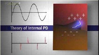
Monitoring the condition of HV insulation in indoor and outdoor switchgear can be achieved by the detection of partial discharge (PD) activity (which leads to deterioration and subsequently failures in such insulation). PD breakdown of insulation produces light, heat, smell, sound and electromagnetic waves.
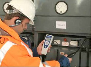
The most practical methods of PD detection on switchgear involve the detection of sound (ultrasonic) or electromagnetic waves (Transient Earth Voltages or TEVs). The detection of partial discharges may be performed using basic go/no go type instruments that measure both phenomena, such as the UltraTEV Detector™, or by far more sophisticated equipment that enables the user to measure, locate and record PD in the equipment being monitored. Examples of the latter include the UltraTEV Plus+™, UltraTEV Locator™ and UltraTEV Monitor™.
The sound produced PD breakdown of insulation can be monitored via ultrasonic detectors. For these to pick up ultrasonic noise they must be in media of similar densities, because propagation of ultrasonics waves between low and high density mediums is poor, due to most of the energy being reflected. Airborne ultrasonic detectors are therefore successful in detecting surface discharge activity, e.g. on an insulator in air, and activity where there is a good acoustic path, e.g. on a dry termination in a vented cable box.
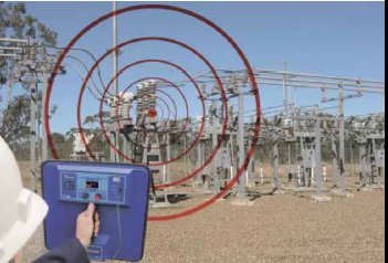
The non-intrusive detection of the electromagnetic wave from PD activity can be carried out using several commercially available instruments.
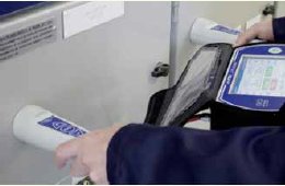
For spot measurements on switchgear, a survey will locate sources of continuous PD activity. A capacitive probe or probes can be placed on the outside earthed metalwork of the switchgear to detect any Transient Earth Voltage (TEV) which is generated on the metal surface when electromagnetic waves propagate out into free space at any opening in the metal cladding. Instruments utilising a single probe can measure the amplitude of the discharge activity, while more sophisticated instrumentation determine the location of the source using a second probe and precedence circuitry within the instrument. Single probe instruments are also available that measure both ultrasonic and TEV discharges.
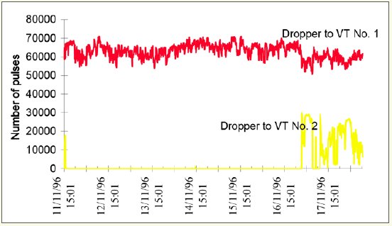
PD activity may be intermittent in nature. A discharge site can remain dormant for many hours and be re-initiated by changes in temperature, by humidity or by a voltage surge. The site can then remain active for minutes or hours before becoming dormant once more. This form of discharge activity is very difficult to detect during a site survey as the measurement period is so short. Instruments are therefore available that can monitor switchgear for extended periods of up to three months or more.
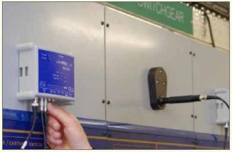
Other instruments are designed to be permanently installed in a substation continuously monitoring partial discharge phenomena, both electromagnetic and ultrasonic, and also humidity, temperature, backup battery condition, etc. The UltraTEV Monitor™, for example, can simultaneously record activity in more than 100 probes, perform analysis internally, and is fully web enabled, allowing monitoring of the switchgear condition anywhere in the world. The unit also has intelligent alarms that can detect trends in the data, and give early warnings of potential problems via the web.
CONDITION ASSESSMENT OF CABLES
Diagnostic tests on cables are usually conducted on complete installed cable circuits and include accessories such as joints and terminations. They may be undertaken for a number of reasons, including commissioning, re-instatement or condition assessment and monitoring. However, it is also important to be clear as to why the test is being carried out and what information it will produce, so that the correct course of action may be followed.
Accurate information on the condition of a cable network is of major importance when planning replacement or even expansion strategies. This avoids unnecessary expenditure and allows resources to be focused on those parts of the network which require most attention. Acquiring quality information to produce a clear picture is likely to be achieved through a combination of failure investigation, sample examination and site testing.
A number of diagnostic techniques are available for cable testing. The quality and detail of the information thus generated varies widely, as does the complexity of measurements and equipment required. DC test methods offer simplicity, due to the small physical size of the test equipment. Withstand testing or pressure testing has been used traditionally to ensure that the circuit is safe to be energised on the distribution network. Some information may be gained from the level of leakage current observed during a test, though this is of limited use and the test is usually conducted as a pass/fail test. Other DC tests – polarisation measurement, sheath testing or of insulation resistance – can give added information.
AC testing, on the other hand, provides a greater level of diagnostic flexibility but brings with it increased size and expense, but the ability to carry out diagnostic testing, particularly PD mapping, provides additional benefits.
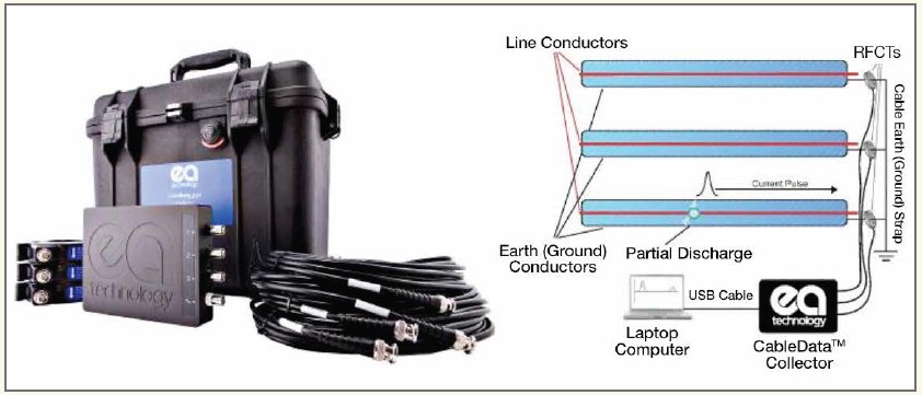
In order to measure PD activity, the cable must be energised at a voltage level of at least the normal working value (U0). PD events are then detected via a high voltage coupling filter connected at the end of the cable under test. The signals are displayed on a digital oscilloscope and transferred to a computer for storage and analysis.
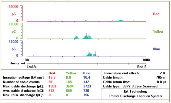
The partial discharge map shown in the Figure 2 allows comparisons between phases and joint positions and highlights potentially problematic areas of the cable circuit. It also demonstrates that in general the areas of cable affected by insulation deterioration are limited. Without this detailed information on the insulation condition it is possible that serviceable cable will be replaced during replacement schemes.
Loss angle measurements allow further diagnosis of the insulation condition under AC test. In a perfect capacitor the current leads the voltage by 90°. For a perfectly resistive load the current will be in phase with the voltage. In reality an insulation system will have some resistive losses, so the current will lead the voltage by an angle between 0 and 90°. The loss angle, known as δ, is the angle between the actual current and 90°. The test is useful for monitoring longer term deterioration or in an event where there has been water ingress into paper insulation; the resistive losses would increase identifying that there is a problem with the cable insulation. The drawback of the technique for cable testing is that the measurement is for the insulation as a whole and does not give an indication of individual defective areas, making the results of limited use. However, the technique is widely used during the testing of transformer windings and bushings.
The diagnostic tests discussed so far concentrate heavily on the assessment of insulation condition. However, it is also useful to have information on other parts of the cable structure. This may be achieved by recovering cable samples for destructive examination when a service failure has occurred. The gradual accumulation of information from an examination programme provides a useful network management tool.
TRANSFORMER TESTING
Transformers are generally reliable pieces of plant and it is rare for one to catastrophically fail shortly after the first warning signals appear. What is more likely is a very gradual deterioration in its condition, which can be adequately monitored through regular maintenance and condition monitoring.
There are a number of on-line and off-line condition monitoring techniques that can be applied to transformers. The off-line techniques such as Frequency Response Analysis, Power Factor Tests and Polarisation Spectrum Tests are generally only applicable to larger or strategically important transformers.
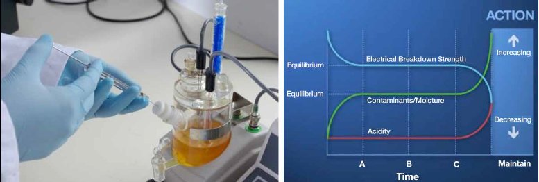
A more common practice involves routine sampling and analysis of the transformer insulating oil. This information provides an indication of the overall condition of a transformer and can help to predict its rate of ageing relative to the loading conditions. There are a number of methods for determining the condition of the oil, including dielectric strength and resistivity measurement together with more specialised tests for the assessment of water, acidity, dissolved gases and furfuraldehyde.
The thermal degradation of oil results in the production of hydrogen, oxygen, nitrogen, methane, ethane, ethylene, acetylene, CO and CO2. Dissolved Gas Analysis (DGA) will detect the levels of these gases in the oil. The ratios of these various gases are used to draw conclusions about the condition of the oil and the presence of any arcing.
In order to assess the rate of degradation of the paper insulation, the furfuraldehyde level in the oil can be measured. The relationship between furfuraldehyde and mechanical strength of the paper is well established and therefore the level of paper degradation as well as the condition of the oil can be assessed from the same oil sample removed from the transformer.
FAILURES
Whilst the failure rates of electrical distribution equipment are fortunately low, the causes and the mechanisms involved are numerous. A failure examination strives to identify the cause and understand the mechanism. Often, the fault damage is extensive, but through attention to detail and the use of forensic techniques it is usually possible to obtain sufficient evidence during an examination to identify the incident resulting in the failure.
The parameters which affect varying items of plant will differ depending upon their function in the network i.e. transformers, switchgear, cabling etc. However, when these fail they all share one common aspect in that the final failure is predominately due to deterioration, or a restriction, of the function of the dielectric – although the initiating mechanism leading to the observed deterioration may be attributed to corrosion, third party damage or even installation or assembly. An understanding of the processes and properties involved in the failures resulting from breakdown of the dielectric is crucial for the future management of the facilities network.
Using the information
The prediction of service failures is very difficult, due to the large numbers of variables involved. With some of the techniques that have been outlined here, it is possible to give an indication that deterioration has taken place and failures are to be expected. On cables with PD mapping it is also possible to predict where these failures are likely to occur. However, the missing link for all plant is being able to predict when the failures are likely to occur.
To address this problem the results of diagnostic testing are often recorded and combined with information about service performance in order that the relationship between the two might be examined. In addition to this there is growing interest in the continuous monitoring of equipment which it is hoped will provide more detailed information about any deterioration taking place and will again relate this to service failures. The cost of instrumentation for continuous monitoring may be a limiting factor for small network operators, but the introduction of a periodic testing and monitoring regime can provide a cost effective and valuable asset management tool.
CONCLUSION
Testing, diagnostics and monitoring of high voltage plant and equipment has developed and there is now a wide range of techniques available. If these are carefully chosen, applied and interpreted they can provide an outstanding tool kit for increasing reliability, reducing costs and prioritising replacement programmes.
For more information see –
http://www.eatechnology.com/improving-network-performance.