

ABSTRACT
Frequent failure of pumps due to the presence of a non-return valve in the discharge line is a common problem which can be avoided by proper trials and inspection during commissioning. A case study on an industrial centrifugal pump illustrates this.
INTRODUCTION
The EDF-owned, coal-fired, 2000 MW Cottam power plant was commissioned between 1966 and1969. Each of its four boiler and turbo-generator (TG) sets has two lift pumps, one for use and another as standby, the in-use pump circulating the condensate water from the steam turbine of the TG set to the boiler. Initially, all four generating units had identical lift pumps (wet wound). However, in the early1980s, and due to maintenance and reliability performance problems, the lift pumps of Unit 1 were changed to conventional centrifugal pumps. This retrofit also resulted in changes to the original steel structural support and associated pipe work. Unfortunately, this arrangement has proved to be unreliable and has posed the biggest maintenance problem for the station, whereas the remaining units with their original unmodified pumps have not presented significant maintenance issues.
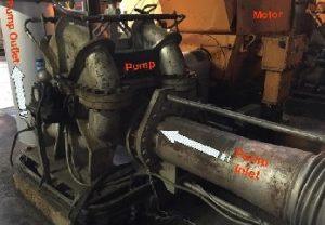
Figure 1 shows the ‘as installed’ centrifugal lift pump, which is driven by a 475 kW motor running at 1487 RPM (24.8 Hz). The pump has six impeller blades and the flow discharge rate is 22500 LPM. The pump shaft is supported through the roller bearings. The outlet pipe is connected to a butterfly non-return valve, as shown in Figure 2.
THE PROBLEM
For the first six months or so the pump performance was satisfactory and it was assumed that the change was meeting the intended requirements. However, after this initial period frequent failures began to be observed, each being repaired and the pump put back into operation quickly on a reactive maintenance basis. The generating unit associated with this pump always needed to be shut down for the work as there was no provisions for on-line isolation of the pump, for maintenance while the other standby pump was put into operation.
Observations of the pump failures has typically been focussed on a growing misalignment between the pump and motor shafts during operation, which led to seal and bearing damage as well as pump joint leakage.
INVESTIGATION
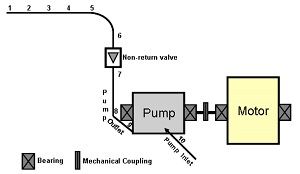
An investigation was undertaken to identify the root causes of this lift pump’s frequent failures. The pump and associated steel pipe work was fully instrumented with twenty accelerometers at ten locations (i.e. at both the vertical and horizontal direction at each point) as shown in Figure 2. Vibration measurements were carried out while the machine was running at its normal operational speed of 1500 RPM (25 Hz). A modal test was undertaken to establish whether any resonant frequencies coincided with the pump operational speed (25Hz) or any of its higher harmonics. It was established that there were no frequencies of relevance and hence resonance was discounted as a root cause of the problem.

The vibration levels observed at the ten locations – covering the pump, non-return valve and associated pipe work – were low during normal operation, i.e. at1500 RPM (25 Hz). The overall RMS velocity at each measurement location was found to be within acceptable limits as per the ISO 10816-7(2009) code. Typical vibration velocity RMS spectra at the pump inlet (Location 10) and outlet (Location 9), in the vertical direction, are shown in Figure 3. Both spectra show small amplitude peaks at 1x (25 Hz) and at its higher harmonics, and a small high amplitude peak at 150 Hz at the outlet pipe (Location 9). The dominant peak at the vane passing frequency – 150 Hz (pump speed of 25 Hz times the number, 6, of pump vanes) – is the likely one near the pump discharge. Hence these observations are as expected and normal for any healthy machine. Hence the pump normal operation may not be involved in the frequent failure.
A further investigation has involved measurement of vibration during the pump change-over, i.e. when the non-return valve operates, to observe the impact of this on the system. A large impact has been noted, the measurement levels at nearly all locations being very high, exceeding the maximum measurement range (±50g) of the accelerometers used.
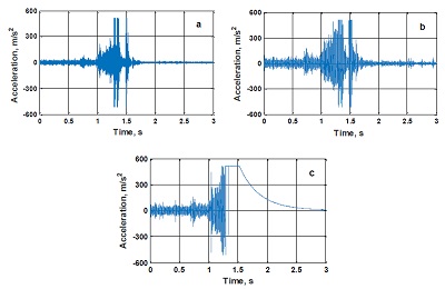
Several typical high vibration responses during the changeover, at Locations 7 (near the valve), 9 (at the outlet pipe) and 10 (at the inlet pipe) are shown in Figure 4. Figure 4(c) clearly indicate that the increase in high vibration starts nearly at 1sec and crosses the accelerometer limit of 50g around 1.2sec, and the impact is so large that, near the valve (Location 7) the accelerometer is not able to respond until 2.5sec, compared to responses measured at other locations. Hence the source of the impact is definitely the operation of the non-return valve. This is a common problem in many old systems where valves are generally not spring-loaded or motor-operated. It occurs when there is no discharge from the pump when water in the pipe, with high total energy head, returns and applies an impulsive load to the non-return valve, i.e. a ‘water hammer’. This high vibration due to valve closure is also transmitted to the pump, as evident from Figures 4(a) and 4 b), and could cause misalignment between the pump and motor shafts, and high stress in the bearings, seals and joints, leading to failure. In short, the non-return valve closure (during pump operation changeover), resulting in the water hammer in the pipe line, is likely to be the main root cause of the pump’s frequent failure.
CONCLUDING REMARKS
It is evident from the in-situ vibration measurements on the pump, and on its connected piping, that the pump has no vibration problem during normal operation. However, the water hammer, due to water back-pressure on the non-return valve during the pump operation changeover, is revealed to be main root cause for the frequent failures of the pump. This is a common problem because these pumps generally operate unattended and/or without any monitoring system (including visual inspection). Phenomena such as, in this case, the water hammer in the valve during pump changeover are going un-noticed. The lesson is that, to avoid future problems, it is important to observe all possible scenarios of a machine’s operation during its commissioning. In the present case two possible solutions to the problem are suggested, viz. (i) spring load the valve or (ii) change to a motor operated valve.
ACKNOWLEDGEMENT
The authors would like to acknowledge the support of the Innovate KTP Project No. 9227 (TSB Project No. 508926).