

The gear has been a fundamental part of technology since Aristotle described them in 330BC. Graham Mackrell, managing director of precision gearing specialist Harmonic Drive UK, offers an update.
Since the industrial revolution, the use of gears has become both commonplace and crucial. From the tiny gearbox in your car’s windscreen wipers to the gears keeping process pumps in oil refineries operational, it is difficult to think of many modern applications in which gears are not a critical component.
The global market for gearboxes and geared motors has grown unceasingly over the last decade, with the only exception being a brief decline during the 2009 financial crisis. This has showed no sign of changing, with the market value expected by Frost & Sullivan to reach $15.67bn in 2017.
To cover such a broad spectrum of applications, gears have diversified since Aristotle first wrote of Archimedes’ gear wheels. Though there are many variations available today, four core types are widely used, each with their own advantages and disadvantages.
The spur gear
The spur gear is the most commonly used gear type. If you were to ask a child to draw a gear, they would almost certainly doodle something resembling a spur gear.
Characterised by protruding teeth, spur gears have a place in everything from washing machines to power plants. This is largely a result of the low cost and ease of installation, but is also due to their constant velocity ratio. Spur gears are capable of transmitting large amounts of power (up to 50,000kW) efficiently.
 Engineers considering using spur gears should think about the nature of their application beforehand. The high backlash of spur gears means that they are unsuitable for environments where precision is essential. Backlash compensation can be fitted but will need regular adjustment throughout the gear’s life. The gear teeth also experience high levels of stress, something that occasionally culminates in teeth breakage.
Though they are efficient in power transmission, this is not the case for space and noise. Spur gears are cumbersome, in both bulk and weight, and this can be a problem in some applications. If a compact gear is necessary or if the end product needs to be lightweight and easily manoeuvrable, spur gears are far from ideal.
Variations of the spur gear include the helical gear, where the gear teeth are not positioned parallel to the axis of rotation, but are curved. This reduces stress and noise, making them much quieter and smoother alternatives. However, because of the angle of the teeth, helical gears produce an axial force, which acts parallel to the axis of rotation and means that a bearing may be required to support the drive shaft.
Advantages: Cheap, widely used, can transmit large amounts of power.
Disadvantages: High backlash, low accuracy, bulky and noisy.
The worm drive
A better solution to meeting a requirement for compactness or light weight would be the worm drive. The worm drive has two parts – the worm gear, a screw-shaped component with a spiral thread at the top of the drive, driving a worm wheel, which looks similar to a spur gear, at 90 degrees to the axis of rotation of the worm gear.
 This design is suited to elevators, lifts and conveyors. It benefits from an ability to self-lock: it lacks the ability to be driven backwards. Other advantages include increased torque and less stress on the gear teeth, owing to the spiral thread.
Where the worm drive falls short is in precision, only offering relatively good precision after modification. (A typical modification involves using a duplex worm gear, where the thread varies in thickness from one end to the other, allowing the user to adjust the backlash to their needs.) However, modifying the system increases stress and wear on the teeth, reducing overall gearbox efficiency. And although the worm drive is more compact than the spur gear, it is still relatively bulky.
Advantages: Self-locking, more compact and higher torque than spur gears.
Disadvantages: Inefficient, still relatively bulky.
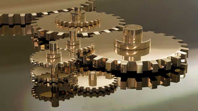
Planetary gears
Planetary gear trains, also known as epicyclic gears, consist of a number of gear wheels – referred to as planet gears – that rotate around a central “sun” gear (usually the driven component), all within an outer ring gear, or annulus.
 Planetary gears are suited to high speed and relatively high accuracy applications such as packaging machines. Here, the typically low gear ratios between 3:1 and 10:1 allow the machine to reach higher speeds with accuracy.
Because of their compact design, planetary gears provide a higher power density than typical gearing systems, as well as over 95% transmission efficiency and increased stability. The torque density of the gear train is relatively high because the load is shared between each planet, of which there are typically between three and five.
The complexity of the design brings disadvantages ,though, in cost and maintenance. As there are more components in these systems they are generally more expensive and need to be maintained frequently.
Fortunately, planetary gears can be improved without the same kind of repercussions that come from modifying worm drives. Harmonic Drive AG has launched a range of enhanced planetary gears that consistently maintain accuracy to one minute of arc through use of a flexible ring gear. This allows the automation and packaging industry to use precise gears that are better suited to their requirements.
Advantages: Great for high speed, high accuracy machines, high efficiency.
Disadvantages: High part count
Strain wave gear
The strain wave gear is essential in applications that require the highest levels of accuracy and power density. These include high precision robots, space rovers, satellites, antenna systems on offshore oil and gas vessels, the pan and tilt camera systems on subsea remotely-operated vehicles and weapon systems in military and defence applications. In these applications, space is at a premium and the most compact gearing system is required.
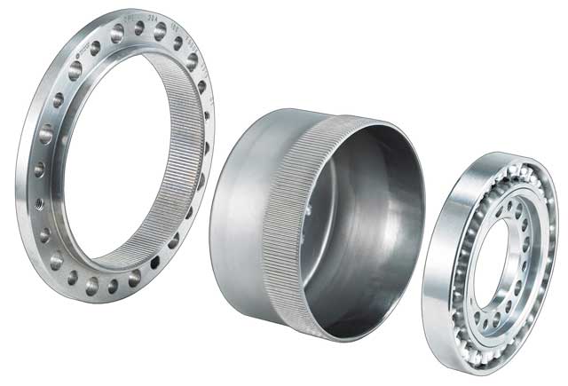
 Also known as a Harmonic Drive after the company of the same name that trademarked the original invention, a strain wave gear consists of just three components: the Circular Spline, a fixed outer ring with gear teeth on the inside; the Flexspline, a flexible inner ring or cup with outer gear teeth; and the Wave Generator, the driven element which takes the form of a specially designed ball bearing race that is fitted on to an elliptical hub. The drive shaft passes through the bored-out centre of the gear assembly.
The Flexspline is a flexible cylindrical cup with external teeth. It is slightly smaller in diameter than the Circular Spline and has two fewer teeth on its outer circumference. The Circular Spline is a rigid ring with internal teeth.
The Flexspline is held in an elliptical shape by the Wave Generator and its teeth engage with the teeth of the Circular Spline at two points across the major axis of the ellipse. As the Wave Generator rotates, the zone of the tooth engagement travels with the major elliptical axis. Each turn of the Wave Generator clockwise moves the Flexspline two teeth anti-clockwise relative to the Circular Spline.
 The versatility of strain wave gears is second to none, with a very low weight, high torque, and single stage ratios that range from 30:1 to 320:1. They can be provided with a large hollow shaft allowing for services or supply lines to be passed through the centre of the gear assembly.
Advantages: High single stage gear ratio, highest accuracy, zero backlash and compactness.
Disadvantages: Most suited to high gear ratio – low speed applications, expensive.
The humble gear has come a long way from the time of Archimedes to become the backbone of modern machinery, and it has been endlessly redesigned and reapplied in the pursuit of perfect performance. As a result, there is now a gear for every business – it’s just a matter of choosing the right one.
Glossary
Velocity ratio: also known as the speed ratio, the ratio of the angular velocity of the input gear to the angular velocity of the output gear.
Backlash: The lash, or play, is the clearance or lost motion between the mated gear teeth due to the gap between them. Backlash is affected by factors such as errors in profile, pitch, tooth thickness, helix angle and centre distance, and run-out. The higher the accuracy of the application, the more important it is to minimise backlash.
Power/torque density: a measure of the torque-carrying capability of the system. It is the ratio of torque capability to volume and can be expressed as Newton-metres per cubic metre. The higher the torque density, the more compact the gear can be for a given output.
Efficiency: The ratio of the energy delivered (or work done) by a machine to the energy needed (or work required) in operating the machine. In gear systems this depends on losses between input and output in the gear system.
Stability: A structure is stable at an equilibrium position if it returns to that position upon being disturbed by an external action.
harmonicdrive.de/en/technology/harmonic-drive-strain-wave-gears/