

Fluke Corporation industrial imaging field application engineer Alexander Bardakov considers best practices for using thermal imaging in industrial maintenance.
Monitoring equipment performance with thermal imaging cameras can reduce the likelihood of unplanned downtime, reduce reactive maintenance fees and equipment repair costs, and extend the lifespan of machine assets. A change in heat pattern is often an early symptom of equipment damage or malfunction and thermal imaging is an important tool in preventive maintenance programs.
Asset maintenance and troubleshooting
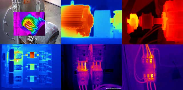
Thermal cameras are very useful for both troubleshooting problems as well as for condition monitoring, for long-term preventive maintenance. They can also be used for assessment of mechanical equipment such as motors, drives and conveyors, but are commonly used for electrical inspection.
Thermal inspection methods
There are three typical methods for infrared inspection: baseline, thermal trending, and comparative.
Baseline thermography requires the technician to scan the equipment when it first commissioned and uses this image as a reference point to look for temperature anomalies in current scans. Once a baseline has been set, thermal trending inspections can be used to compare how temperature is distributed in the same components over time, helping to plan future maintenance schedules.
Comparative thermography involves scanning similar equipment working under similar conditions and compare the results. Once you have three or more pieces of equipment operating under similar conditions it is relatively easy to pick up an anomaly.
Electrical panels
When conducting routine maintenance of electrical panels, the primary job for the maintenance technician is a visual inspection. Under-sized conductors, loose connections or excessive current flow cause heating. Signs of scorching or discoloration of the panel cover, components or component connections having changed colour due to heating are a good indicator of a problem in the circuitry.
Thermal imaging
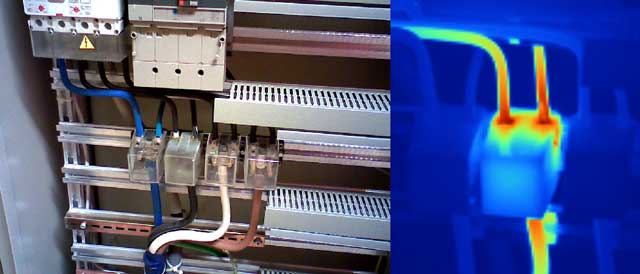
Following a visual inspection, the next step would be to capture thermal images of all electrical panels and other high-load connection points such drives, disconnects, controls, and so on. Where higher temperatures are discovered, follow that circuit, and examine associated branches and loads.
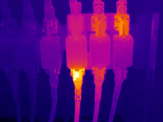
A good rule of thumb when making a comparison of increased temperature on a thermal image, is anything five degrees or more above ambient temperature may indicate an electrical fault. This is a rule of thumb used to indicate candidates for further investigation and experience is often the best guide.
Ideally, electrical device checks should be made when they are fully warmed up and at steady state conditions with at least 40% of the typical load. That way, measurements can be properly evaluated and compared to normal operating conditions. Where possible check panels and other connections with the covers removed to improve the assessment as thermal cameras read only the surface temperature.
Check current and voltage
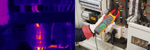
When a thermal image shows an entire conductor is warmer than other components in a circuit, the conductor could be undersized or overloaded. The next step in diagnosing the problem is to measure the current and voltage using appropriate tools to assess the load and compare with the conductor rating.
To measure the electrical current use a clamp meter and a multimeter with a clamp to check the voltage. On the voltage side, check the protection switchgear for voltage drops. In general, the voltage drop should be within 10% of the nameplate rating.
From these measurements an assessment can be made as to the cause of heating. If the component is not over-loaded this could indicate a lose connection. A raised temperature at a connection could indicate it is loose, causing an increased resistance.
Useful tools
Thermal imagers are making maintenance tasks easier by including features like asset tagging. The thermal imager is equipped with a digital camera for scanning QR codes or bar codes on cabinets for filing and storing thermal images and making notes of tests and results. It is useful to have an easy way to identify which thermal image applies to which cabinet, particularly when they all look so similar.
To find out more about thermal imaging for electrical systems follow https://www.fluke.com/en-gb/learn/blog/thermalimaging/electrical-systems