

ABSTRACT
This article looks at DC motors and drives and how they can be used and maintained in the modern industrial environment. This proven technology still keeps many applications producing and working efficiently. With modern microprocessor-based control these motors can be added to any maintenance plan and, with some planning, can follow an active and accurate predictive maintenance programme. The article considers the technology and the methodology to show how the key elements of current, speed and temperature can be monitored and evaluated as part of a comprehensive maintenance regime.
Before AC drives arrived, the only way to vary the speed of an industrial motor was to use a DC motor and a DC drive. One of the reasons that DC drives have been replaced by AC drives and motors has been due to the perceived issues of DC motor maintenance. However, in the modern industrial world the need to regularly check and access DC motors has in general been dramatically reduced, and the fallout has not been very great at all.
DC motor characteristics and maintenance
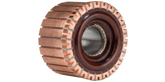
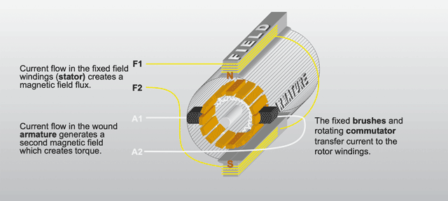
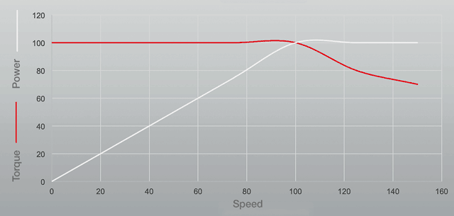
The DC motor requires brushes to provide the main connection of voltage and current to the armature (or rotor) of the motor. These wear over time, but they are one of the main reasons DC motors are still prevalent in industry. Having a direct and mechanical connection to the armature of the motor means that the magnetic current is always at 90 degrees to the magnetic field of the motor; this cannot change because the motor is mechanically designed this way. As a result torque remains constant throughout the speed range all the way from zero speed. Unlike an AC motor and inverter, which has to compensate for slip, the DC motor just keeps performing. By considering the brushes of the motor it is possible to assist their longevity.
First, if an application is new or untested the brush length can be measured over time (maybe a two-month period) and wear measured. If the active length of the brush is known, it is not difficult to calculate an operating time period for the brush life. If the brush is lightly loaded it will wear slightly more quickly, so either this can be managed or the brush can be replaced with a harder compound. Once established, it is reasonably easy to control and maintain this.
If this is not considered, when the brush gets to a critical length some erratic performance in the motor may be seen. If this is caught in time, it is a common strategy to change the brushes at this point. This is often all that is needed. However, in this method there is some risk of damage to the commutator.
The other part of the DC motor that may need some attention is the blower filter. Most DC motors are classified as IC06 under the standard DIN EN 60034-6, which means the blower on the motor pushes air through the motor to cool it. This gives additional motor protection because it is similar to having a purged motor. Debris cannot get into the motor because it is under positive pressure.
It is therefore essential that the filter is maintained (by replacing the element). If this is done, the blower arrangement means the cooling of the motor is maintained throughout the speed range. It is not unusual to see DC motors and drives operating with a 100:1 range between maximum to minimum motor speed. A standard AC motor would struggle to give more than between 3:1 and 5:1 without additional cooling.
Monitoring DC motors
The mechanical design of the DC motor provides some reasonably easy methods of monitoring. The air flow can be externally measured at the motor blower. The blower current can be externally measured. Brush length is better calculated manually, but brushes can be fitted with shunts to give an early indication of wear, and a microswitch can be fitted to the spring to monitor brush tension.
When considering active control and monitoring of applications using DC motors and drives, three main parameters can be used. These are current, temperature and speed.
The speed and the current of the motor are configured and controlled by a proportional–integral–derivative (PID) control loop in the drive, with the proportional term to alter and control the gain, the integral term to set steady state error and the derivative term to set long term stability. These PID blocks are known as the speed loop and the current loop.
As mentioned previously, the current generated in the motor is mechanically maintained in the armature, so for a DC motor current is directly proportional to torque throughout the whole motor speed range. It is also accurate and controllable. On an AC motor and drive it is not unusual for the accuracy range of the current loop to be in the order of ±20%, which makes the current loop almost impossible to control in a dynamic application.
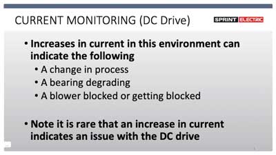
Using a DC motor and drive, the accuracy is around 2/3% and is fully controllable. This makes monitoring of current a very reliable indication of performance. Swings in current can be load dependent, but if a model of the load has been created it is reasonably easy to map this against actual current and plot the differences as a trend. Current can fluctuate if the brushes are excessively worn, but if proactive maintenance is performed production disruption from this cause can be kept to a minimum.
If brush wear is ruled out, increases in current can indicate a change in process which may not require any action, but may also indicate a bearing degrading or a blower getting blocked. It is rare that an increase in current is due to an issue with the actual DC drive.
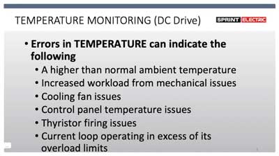
A similar mapping and plotting of trends can be done with regard to temperature. This can be extended to include control panel temperature and ambient temperature, again allowing early analysis of potential issues.
Errors in temperature can indicate a number of potential issues and these need to be balanced against operating conditions. So, for example, the temperature values need to be scaled according to ambient temperature. Machines can be operated in quite a wide temperature range depending on the process and the time of year. Temperatures can increase due to increased workload and also if the equipment is operating in excess of its overload limits. A rise can also indicate cooling fan issues or that the DC drive thyristors are not working correctly.
Monitoring the internal temperature of the control panel holding the electronic equipment gives an indication of component parts operating incorrectly or out of specification.
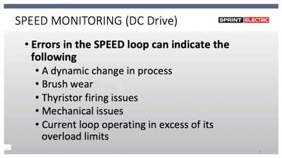
Speed can be a little harder to use as an indication of maintenance issues because it can vary widely within a process under normal operation. However, the actual speed and the expected speed are available and can be monitored and compared.
As the speed loop and current loop are completely separate in a DC drive, this comparison is not affected by other parameters, so setting a limit based on the error between the expected and actual speed, and creating an alarm if out of limits, can give an early indication of possible problems. This is especially easy in tachogenerator or encoder feedback.
Errors in the speed loop can indicate dynamic changes in the process, brush wear, thyristor firing issues, mechanical problems and the current loop operating in excess of its overload limits.
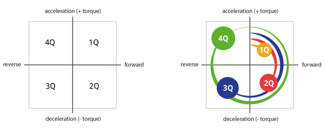
The DC drive has the ability to control in all four quadrants of the control cycle (see above). The four quadrants are forward, reverse, positive torque and negative torque. In other words the motor can be controlled to drive an application and can also be controlled to brake it, and both these can be done continuously. This is different from an AC drive, which works by taking AC, converting it to DC and then using the DC to generate a simulated AC output. As a result, if an AC motor is braked it puts voltage back on the DC link, and this needs to be braked with resistors or the drive will trip out. It cannot brake continuously.
This feature of the DC drive is imperative in applications such as continuous process lines for cable and wire, paper, plastic or steel, to name but a few, where multiple drives are used to control the line. The ability to continuously brake and drive removes the chance that the motor can be overhauled during operation. As a result the actual speed and intended speed are very closely matched under normal operation of a DC-driven system, again making it stable and easier to measure error.
By combining current, speed and temperature with data on the mechanical properties of the DC motor – such as air flow (from the blower), blower current, brush length, and motor temperature via the internal thermistor – and profiling these against expected values, it is possible to get a fairly accurate predictive error report.
Even though all this motor and drive data is available for the application, it is still necessary to compare the data with expected results. Modern software allows the ability to produce a model (or a chart) of the application measuring the parameter values during the process and then setting maximum and minimum operating limits at each point of the process. As long as the value stays within these limits there is no alarm. Double limits can also be added, so that one can be an alarm and the second a trip. Frequency of values can also be monitored and used as part of the monitoring process to make it more robust. This process is also known as mapping.
Always when producing a predictive maintenance model it is necessary to make efforts to avoid nuisance alarms and tripping.
Using trend analysis and alarm models is valuable in avoiding downtime, but models need to be accurately constructed to avoid the risk of being ignored or overlooked. Some reporting errors are time-critical but many errors can be overlooked if they are infrequent. This is why modelling is required.
It is worth noting that where Sprint Electric has been directly involved in predictive and preventive maintenance projects, and has looked at mapping a production process, one of the biggest influencers is the machine operator. Even on the same line, different operators can produce greatly different mapping. As a result it is recommended that the process and design starts with a requirement for the operator to log in before production begins, or if operators change mid-shift. The correct mapping can then be used and matched to the operator, so reducing spurious results.
Conclusion
Modern electronics in DC drives allow a lot more flexibility in monitoring and maintaining existing DC motors. This, coupled with the ability to compile and collate a great deal of data during use, means they will continue to be used for many years to come.
This is a summary of a presentation given by the author at the Maintec Exhibition at the NEC, Birmingham, October 2019.

Neill Drennan is the business development manager at Sprint Electric. He joined the Sprint team two years ago and has built an entire career in the industrial automation industry, including over 23 years at Parker SSD together with experience working at SIEI UK, Eurotherm Drives and Renold Electronics. Mr Drennan originally started as a mechanical engineer apprentice but re-trained in electrical engineering. He later took a Business Studies degree (BA Hons). He works globally, working with distributors as well as supporting users on individual projects.
Contact details: neill.drennan@sprint-electric.com.
Sprint Electric
Founded in 1987, Sprint Electric designs and manufactures a wide range of digital motor control solutions up to 1MW, covering both single phase and three phase, regenerative and non-regenerative applications. Awarded the Queen’s Award for Enterprise in 2009, Sprint Electric has a global network of distributors providing exceptional worldwide support and sales from stock. Its UK manufacturing facility and HQ are in the south of England.