

Model-based voltage and current analysis is a powerful method of condition monitoring for rotating electric equipment, says Faraday Predictive operations director Geoff Walker.
Model-based voltage and current analysis (MBVI) is a condition monitoring and diagnostic technique that provides a useful alternative to vibration monitoring, particularly suitable for inaccessible assets where it is difficult to take vibration readings. It detects mechanical, electrical and operational faults. It represents the next generation on from motor current signature analysis (MCSA).
MCSA is a well-established technique, with over 30 years’ industrial application. It has mainly been used for identifying developing problems in motors, such as rotor bar cracking. MCSA works on the basis that faults in the motor result in distortions of the motor current, at characteristic frequencies for each fault. By analysing the frequencies of these distortions and comparing them with known fault frequencies, conclusions can be drawn about the presence and severity of these faults.
MCSA analyses a frequency spectrum of the current waveform. If the waveform were perfectly sinusoidal, this spectrum would appear as a single peak at the line frequency only, as shown in the first row in Figure 1 below. Any distortions to the current waveform appear as additional peaks, at frequencies related to the characteristic frequency of the phenomenon causing the distortion, as shown in the second row in Figure 1:
By assessng the size and frequency of the additional peak, the probable cause and its severity can be deduced.
Analysing the current waveform alone limits MCSA’s ability to identify problems when the applied voltage is distorted, because this also introduces distortions into the current that have nothing to do with faults in the motor or driven equipment.
Distorted voltage waveforms are increasingly common in industrial environments, often resulting from the use of inverters to provide variable speed control. These can introduce significant distortions to the voltage waveform, as shown in figure 2 above.
The distorted three-phase voltages (larger, darker coloured traces) create distorted three-phase currents (smaller, paler traces). Conventional MCSA on these currents would show a mass of peaks which would wrongly suggest all sorts of faults with the rotating equipment.
The distortions caused by the inverter can also affect the electrical supply network from which it is drawing power, meaning that other equipment connected to the same network will also receive a distorted supply.
Conventional MCSA cannot work effectively with distorted voltages like this. Instead, MBVI should be used.
Model-based voltage and current analysis (MBVI)
Model-based voltage and current systems (abbreviated to MBVI rather than MBVC, because I is the standard symbol for electric current), such as the Faraday Predictive S200 system, use a mathematical model of the relationship between current and voltage to pick out those distortions on the current waveform that have not been caused by distortions on the voltage waveform, and therefore must have come from the motor and driven equipment system.
Figure 3 (shows in pink a slightly distorted voltage waveform and in bolder red the rather more distorted current waveform. The orange line across the middle represents the distortions on the current waveform that have not been caused by distortions on the voltage waveform. Note that this residual current is based on voltage and current on all three phases, although only one phase of voltage and current is included in this plot for clarity.
The residual current is directly analogous to a raw vibration signal. And like vibration analysis, by turning this time domain plot into a frequency spectrum it is possible to identify the frequency and magnitude of the signals present. By matching these frequencies against the characteristic frequencies for known faults, the phenomena present in the equipment can be identified. By plotting trends over time, developing faults can be studied, and predictions made about the time remaining before failure occurs. This allows maintenance interventions to be planned, avoiding unplanned downtime.
Typical MBVI systems provide:
- overall assessment of current equipment condition (mechanical, electrical, operational)
- identification of faults present and assessment of their severity
- plotting of trends and forecasts of severity levels of each individual fault
- energy monitoring and power supply quality monitoring
- identification of energy wasted by each fault – allowing cost-benefit justification of a fix.
Advantages of MBVI systems
Because MBVI systems eliminate the effect of the voltage supply, they also allow better discrimination between the remaining signals. In summary, MBVI systems provide the following advantages over conventional MCSA:
- ability to diagnose faults in inverter-driven equipment without spurious results
- ability to identify smaller faults – not just broken rotor bars, but very similar faults to those detectable by vibration monitoring
- ability to provide automated diagnostics and forecasts with specific advice on each fault type
- ability to make use of information on all three phases – allowing identification of additional faults.
MBVI systems can be an alternative to conventional vibration monitoring systems, with advantages from the fact that the installation is done in the switchgear, making the equipment much less vulnerable to damage, and avoiding the need to have direct access to inaccessible equipment. In addition, changes in speed and load, which can affect vibration results, can be automatically detected and compensated for. Advantages include:
- ideal for monitoring inaccessible equipment
- ability to deal with varying speeds and loads
- ability to detect not just mechanical, but also electrical and operational problems
- ability to measure energy consumption and identify energy wasters
- less vulnerable to damage to sensors
- no need for long wiring connections to equipment
- a single sensor per item of equipment.
Applicability
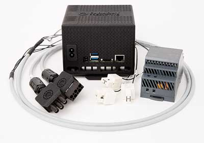
The technology is available both in permanently installed versions, like the Faraday Predictive S200 series, or in a portable kit like the Faraday Predictive P100 kit, shown below.
MBVI systems can be used on almost any rotating equipment driven by electric motor. They are equally applicable to generators, providing information not just on the generator but also the prime mover driving the generator.

MBVI systems are particularly applicable where conventional vibration monitoring is difficult or impossible. Examples include inaccessible equipment, such as submerged pumps, borehole pumps, in-tank pumps, in-duct fans, cryogenic equipment, or equipment in isolated locations, such as roof-mounted fans.
In short, MBVI systems can be a powerful condition monitoring and diagnostic tool, for both permanently installed or portable solutions.
info@faradaypredictive.com | tel: 0333 772 0748
www.faradaypredictive.com